What is BME280
BME280 is a sensor to measure temperature, pressure, and humidity, which is mainly for monitoring an ordinal environment.
micro:bit itself also has a temperature sensor. However, it is for monitoring the temperature of CPU to prevent from overheating, which will report you a higher temperature than the environment when you run some tasks on the CPU. On the other hand, BME280 will report you pretty precise measurement result, since the each of the unit has its own data to calibrate measurement result.
You can refer the following link for more information about the device.
https://www.bosch-sensortec.com/bst/products/all_products/bme280
Set up
What you must have
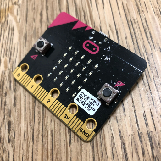
- micro:bit
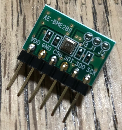
- BME280 i2c board
What you may nice to have
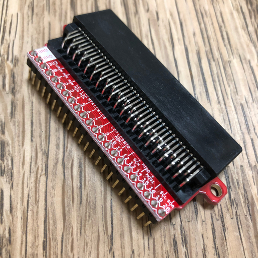
- a breakout board for micro:bit
breakout board exposes all terminals of the connected micro:bit to the pins that can be connected to a breadboard safely.
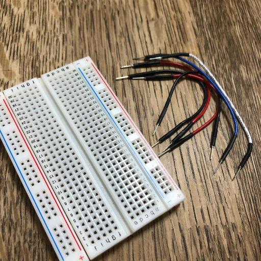
- a breadboard and jumper pins
breadboard is useful to create a test circuit without soldering.
How to connect a BME280 I2C board to your micro:bit
micro:bit has two terminals to supply power to BME280 I2C board, which are called “+3v3” and “GND”, also it has another two terminals to communicate data between your micro:bit and BME280, which called “SCL” and “SDA”.
You can visit the following link to refer where the terminals are on your micro:bit.
http://microbit.org/guide/hardware/pins/
On the other hand, your BME280 device will be vary, so I cannot describe here what pin should be connected to what pin of your BME280 device. However, most of a device should have the following connections, if you have a difficulty to connect your device, try asking the people around you, don’t hesitate.
- “+3v3” -> “VDD” (This is to supply +3V power to your BME280 from micro:bit)
- “GND” -> “GND” (This is to supply +3V power to your BME280 from micro:bit)
- “SDA” -> “SDI” (This is an I2C data connection.)
- “SCL” -> “SCK” (This is an I2C clock connection.)
My case
OK, then, let’s see how my case was.
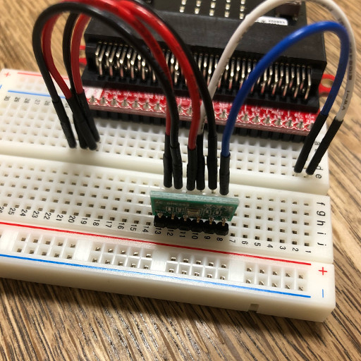
- Insert micro:bit to the card edge connector of the breakout board.

- Connect the breakout board to the breadboard.
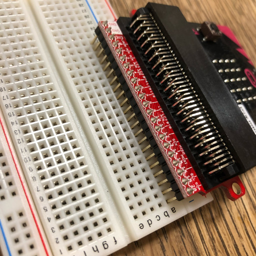
- Connect the BME280 board to the other hand of the breadboard.
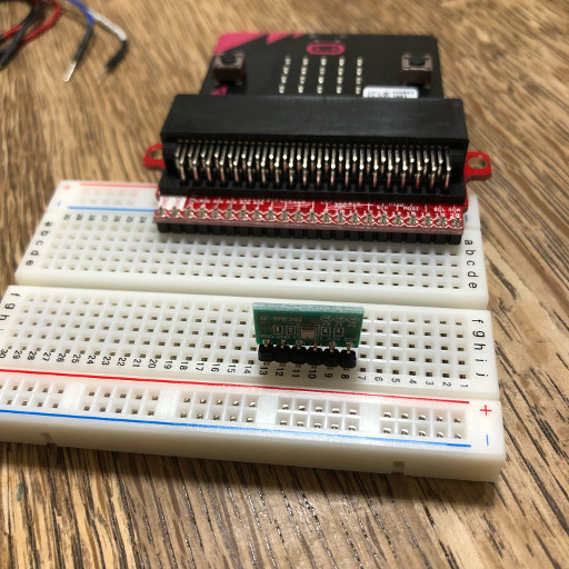
- Connect jumper pins to make the circuit described above.
In my case, there were two more pins needed to connect to “GND” and “+3v3” respectively.
The one was to select I2C address of BME280 board, which was 0x76. The other was to activate I2C bus.
Let’s code!
Finally we have prepared to use our BME280. Here is the step to get work the sensors.
- Open https://makecode.microbit.org on your browser.
- Click gear icon and select “Add Package…”
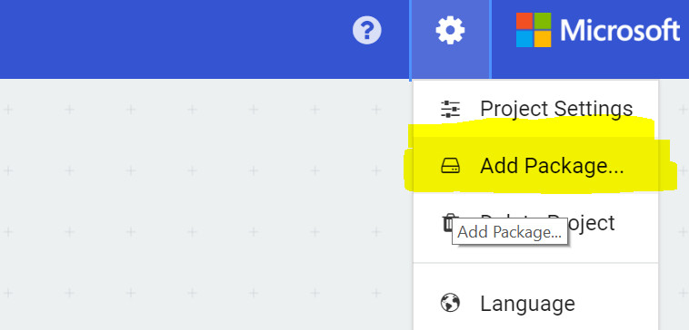
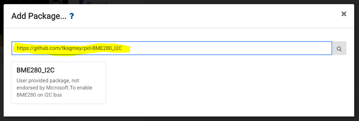
- Enter the following URL to the text box.
https://github.com/tksgmsy/pxt-BME280_I2C
Unfortunately, this is not officially approved package, so you’ll see that message.
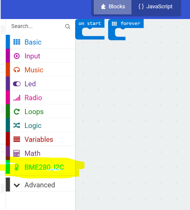
- Once you’ve successfully imported the package to your project, you’ll see that new row on you block coding pane.
- Lastly, here is my example code.
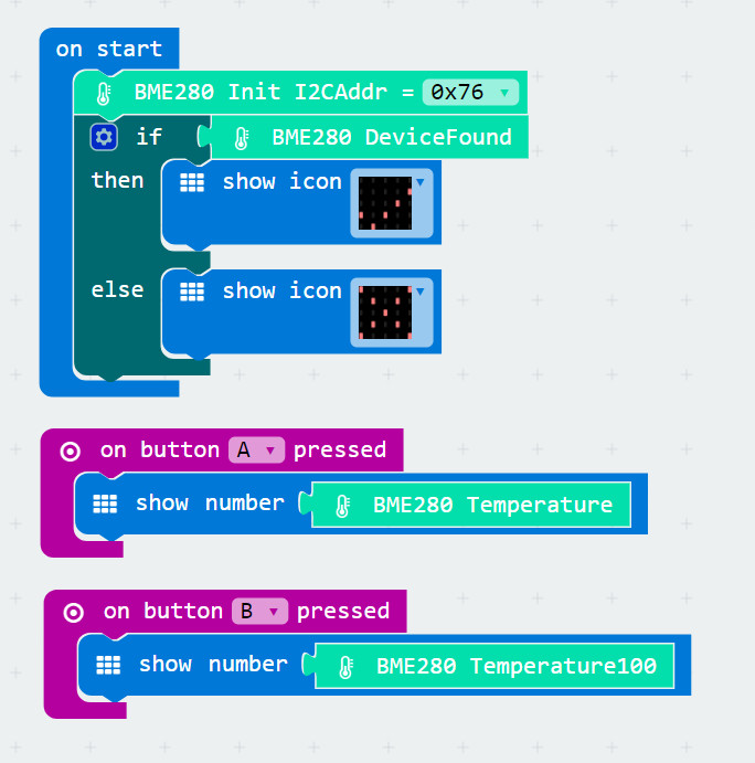
Notice that you must need to select proper I2C bus address of your BME280 in “Init” block, which should be either 0x76 or 0x77.
If your BME280 is found on the I2C bus and initialized properly, “DeviceFound” block will return “true”, otherwise return “false”. So, you can check it by looking into the icon after booting your micro:bit.
When pressing “A”, you’ll see the temperature measured by BME280 in degrees celsius.
When pressing “B”, you’ll see hundredfold of the temperature, which is to tell you the temperature with two decimal place. - Have fun!
There are other blocks to measure pressure and humidity, additionally to set some functionalities of BME280. I recommend you to check the data sheet of BME280 before using those blocks. You can find it from the following link.
https://www.bosch-sensortec.com/bst/products/all_products/bme280
Hope you to enjoy your block coding life!
By the way, this page and cusom package were written by a father of an elementary school boy in Japan for free research on summer vacation. :)